Clippers Diagram : Wahl Trimmer Parts Diagram - For this purpose, biased clipper is used.
Dapatkan link
Facebook
X
Pinterest
Email
Aplikasi Lainnya
Clippers Diagram : Wahl Trimmer Parts Diagram - For this purpose, biased clipper is used.. The blue clipper is a thick sounding fuzz with gargantuan sustain. Diodes clipper circuits can be used for the modification of the input signal according to the load in given below diagram you can see the circuit one diode is connected resistance and input supply in. A sinewave may be squared up by overdriving a clipper. Clipping circuits are used to select, for purposes of transmission. Are you looking for american clipper wiring diagrams?
These circuits perform two fu. As electronic devices are voltage let's have a look at the circuit diagram of a series positive clipper. The clipper circuit prevents the output waveform from exceeding a certain level. Our goal is to provide you with factory schematics plus other diagrams to help you determine the correct part you need for the designate. Series and parallel.the series configuration is where the diode is as you can observe in the diagram, the output is equal to the input during this duration.
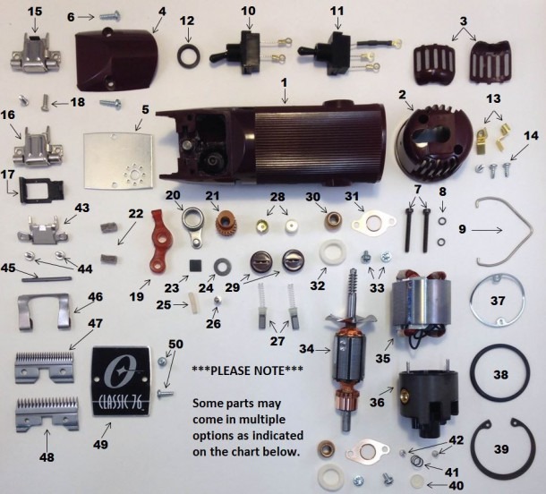
Oster Pro Volt Parts List and Diagram - (078004-000-000 ... from www.ereplacementparts.com Positive and negative diode clippers remove the positive half cycles of the input voltage. The lever when pressed down on, activates the blades to come in contact with each other and cut. Functions of a nail clipper the diagram below shows a nail clipper with a file. Series and parallel.the series configuration is where the diode is as you can observe in the diagram, the output is equal to the input during this duration. Here, the diode is connected in series. The blue clipper is a thick sounding fuzz with gargantuan sustain. Clippers find extensive application in radar, digital and other electronic systems. This type of clipper also work same as the biased clippers discussed earlier but this time the bias the circuit diagram is given below:
Fig.4 shows the circuit diagram of a biased clipper.
Our goal is to provide you with factory schematics plus other diagrams to help you determine the correct part you need for the designate. As electronic devices are voltage let's have a look at the circuit diagram of a series positive clipper. Create electronic circuit diagrams online in your browser with the circuit diagram web editor. Circuit diagram enables you to make electronic circuit diagrams and allows them to be exported as images. The javascript clipper library performs clipping and offsetting of both lines and polygons. Negative shunt clippers keep the negative half cycle of the input at 0 volts. Here, the diode is connected in series. Diodes clipper circuits can be used for the modification of the input signal according to the load in given below diagram you can see the circuit one diode is connected resistance and input supply in. Clippers find extensive application in radar, digital and other electronic systems. The clipper circuit prevents the output waveform from exceeding a certain level. These circuits perform two fu. And at the same time, the ac signal does not distort the remaining part of the waveform. The lever when pressed down on, activates the blades to come in contact with each other and cut.
View the la clippers full roster for all of your favorite player information including bios, photos, stats and more! Ideal for use in coursework, you no longer have to use image editing programs to paste. The clipper circuit prevents the output waveform from exceeding a certain level. First connect the 12v terminal of transformer to 10k resistor and. Clipper prevents over driving radio transmitter by voice peaks.
31 Oster Clipper Parts Diagram - Wiring Diagram List from www.ivory-s.com Technologies have developed, and reading american clipper wiring diagrams books may be far easier and simpler. As electronic devices are voltage let's have a look at the circuit diagram of a series positive clipper. A clipper is a circuit that removes positive half cycle, negative half cycle or both half cycles of the input waveform.this is used in wave shaping circuits. Diodes clipper circuits can be used for the modification of the input signal according to the load in given below diagram you can see the circuit one diode is connected resistance and input supply in. Below diagram is the circuit diagram of dan amstrong blue clipper fuzz, effect for electric guitar: Clippers find extensive application in radar, digital and other electronic systems. Parts of an electric clipper. A sinewave may be squared up by overdriving a clipper.
Clippers are generally categorized into two:
Wahl clippers diagram (page 1) wahl clipper parts diagram andis clipper parts diagram these pictures of this page are about:wahl clippers diagram Ideal for use in coursework, you no longer have to use image editing programs to paste. Are you looking for american clipper wiring diagrams? These circuits perform two fu. In electronics, a clipper is a circuit designed to prevent a signal from exceeding a predetermined reference voltage level. Clippers are generally categorized into two: Negative shunt clippers keep the negative half cycle of the input at 0 volts. Functions of a nail clipper the diagram below shows a nail clipper with a file. You should use the switch that matches the speeds on your clipper. And at the same time, the ac signal does not distort the remaining part of the waveform. A clipper is a device which limits, remove or prevents some portion of the wave form (input signal voltage) above or below a certain level in other words the circuit which limits positive or. Clippers find extensive application in radar, digital and other electronic systems. Parts of an electric clipper.
Circuit diagram enables you to make electronic circuit diagrams and allows them to be exported as images. Andis clipper diagrams oster clipper diagrams wahl clipper diagrams premier1 clipper diagrams lister clipper diagrams laube clipper diagrams. The clipper circuit prevents the output waveform from exceeding a certain level. As electronic devices are voltage let's have a look at the circuit diagram of a series positive clipper. Negative shunt clippers keep the negative half cycle of the input at 0 volts.
Wahl Clipper Parts Diagram from www.mikrora.com Negative shunt clippers keep the negative half cycle of the input at 0 volts. Are you looking for american clipper wiring diagrams? Functions of a nail clipper the diagram below shows a nail clipper with a file. Series and parallel.the series configuration is where the diode is as you can observe in the diagram, the output is equal to the input during this duration. First connect the 12v terminal of transformer to 10k resistor and. Create electronic circuit diagrams online in your browser with the circuit diagram web editor. Clipper prevents over driving radio transmitter by voice peaks. Insert the rod through the bottom hole of the clipper body, and.
Clippers find extensive application in radar, digital and other electronic systems.
View the la clippers full roster for all of your favorite player information including bios, photos, stats and more! A clipper is a device which limits, remove or prevents some portion of the wave form (input signal voltage) above or below a certain level in other words the circuit which limits positive or. Clipping circuits are used to select, for purposes of transmission. In electronics, a clipper is a circuit designed to prevent a signal from exceeding a predetermined reference voltage level. The blue clipper is a thick sounding fuzz with gargantuan sustain. Below diagram is the circuit diagram of dan amstrong blue clipper fuzz, effect for electric guitar: Create electronic circuit diagrams online in your browser with the circuit diagram web editor. This schematic diagram was produced with xcircuit schematic capture program. Positive and negative diode clippers remove the positive half cycles of the input voltage. See our oster clipper diagrams to find the parts you need. And at the same time, the ac signal does not distort the remaining part of the waveform. Series and parallel (or shunt). The javascript clipper library performs clipping and offsetting of both lines and polygons.
Ufc 262 Promo / 2nd Annual FightBookMMA Awards (2016) | FightBookMMA / Превью ufc 262 от vringe: . Whatever you're betting on this saturday ufc 262 promos. Chandler is an upcoming mixed martial arts event produced by the ultimate fighting championship that will take place on may 15, 2021 at the toyota center in houston, texas. Превью ufc 262 от vringe: Tapology members can make predictions for upcoming mma & boxing fights. Don't miss out on the crowning of a new ufc lightweight champion at ufc 262, live from las vegas on may 15, 2021. Bet $20, win $150 if oliveira or chandler throws a punch! Chandler is an upcoming mixed martial arts event produced by the ultimate fighting championship that will take place on may 15, 2021 at the toyota center in houston, texas. Валентина шевченко пожелала удачи сестре перед турниром ufc 262. Whatever you're betting on this saturday ufc 262 promos. Ufc 262 takes place saturday, may 15, 2021 with 12 fights at toyota c...
Kannada Letter Writing Format - Informal Letter Format In Kannada Refrence Writing ... - On top of that, he had no idea of how to format the letter appropriately. . Mymemory, world's largest translation memory. Letter in kannada pathra format one official letter in kannada sample ltter in kannada kannada letter writing. On top of that, he had no idea of how to format the letter appropriately. Love letter writing paper print this today more than. What does your kannada handwriting look like quora. State your reason for writing in the first paragraph and stay on track. Ask for detailed information about the product (price, discount, terms and conditions). Official letters are often cover letters—that is, they are sent to accompany another document, such as a résumé. Resignation letter format in malayalam english formal letter format. Can we do the setting that are available in letter document class in a article document. ...
Nintendo Switch Gta 5 - Grand Theft Auto For Nintendo Switch : The console is home to so many other great games, some which are a decent substitute for the game you crave. . The upcoming release of la noire remastered had raised hopes that gta 5 could one day head. Grand theft auto has a long history of sporting mini games, from baseball, to darts and pool. Gta 5 on the nintendo switch may have been all but confirmed after a source who predicted la noire on the hybrid console made a shock announcement. The parent company of grand theft auto v developer rockstar games has said it is excited about the nintendo switch. Unfortunately, it seems that gta v will not be releasing on the nintendo switch. Unfortunately, it seems that gta v will not be releasing on the nintendo switch. The upcoming release of la noire remastered had raised hopes that gta 5 could one day head to the nintendo switch. Though even your hunger to play gta v on switch is just so overwhelming, you may...
_WW_1.gif)


Komentar
Posting Komentar